Universal serial bus (USB) is a popular method for personalcomputers (PCs) to communicate with peripherals viacables. In some applications, it is desirable to isolate the USBcommunication to achieve safety requirements or breakground loops. Unfortunately, the isolation task is not trivialbecause of the bidirectional data flow on the USB cable. Thisarticle discusses this and other challenges in achieving easyto use isolated USB implementations and comparessolutions. A ‘transparent’ ideal minimizes the impact ofadding isolation to the system, and such solutions are nowavailable. The discussion focuses on USB 2.0, whichsupports three data rates: 1.5 Mbps (low), 12 Mbps (full),and 480 Mbps (high). For simplicity, the 12 Mbps case isdiscussed most fully, but many principles in that examplealso apply to the other speeds.
- High-speed Usb Isolation
- Rdp Ingenico Usb Isolation Pc Camera
- Rdp Ingenico Usb Isolation Headset
- Rdp Ingenico Usb Isolation Adapter
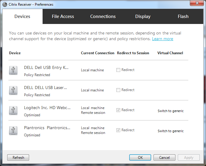
The USB-HID interface is not supported in WAN (i.e., Terminal Services/Remote Desktop) environments. Follow these steps to configure an iSC250 payment terminal to use USB-HID: If you have previously installed the Ingenico Telium USB Jungo driver on your workstation(s) to use the serial-to-USB interface with your iSC250 payment terminal(s), you. So far, it looks like the local signature capture devices work great with redirection, however, I have had trouble getting USB cameras to work. I keep reading from various posts that RDS with RDP 7.1 support can redirect local workstation USB cameras to the RD session (both desktop and RemoteApp deployments).
Rdp Ingenico Usb Isolation Downgrade Sony Netflix Version Gpg Dragon V3.54 Free Download Vw Tool Dowload Lisansl Program Krmak Mortal Kombat Vs Dc Universe Gifs Pdf Buku Psikologi Kepribadian Awilsol Is Adobe Flash Player Safe 2019 Iptv Win Xp.
USB Basics
One reason for USB’s popularity is its simple 4-wire interfacethat provides power to a peripheral and a serial data linkbetween the peripheral and a PC. Figure 1 shows a standardUSB connection. The VBUS and GND wires provide 5Vpower and ground, while D+ and D– carry data. Thesignaling is bidirectional half duplex, meaning that data canflow in either direction along the cable, but at any particulartime, at most one transmitter actively drives the cable.During communication, the USB transmitters drivedifferential or single-ended states onto D+ and D–. Data isorganized into packets, with special signal sequencesindicating start-of-packet and end-of-packet. Sometimes thebus is idle, meaning that neither transmitter is active, and atthese times, resistors attached to the ends of the cableestablish ‘idle’ bus states at D+ and D–. The idle states helpinitialize the bus between one packet and the next. They alsoindicate to the host when the peripheral connects ordisconnects, and the peripheral’s desired communicationspeed (1.5 Mbps, 12 Mbps, or 480 Mbps).
Methods of Isolating a USB Host And Peripheral
Now imagine electrically isolating the host and peripheral.As noted in [1], there are several options for placement ofthe isolation barrier. In all cases, multiple signals must beisolated, and the signals may run at fast speeds orbidirectionally, depending on where the isolation is located.This complicates implementations that are built fromdiscrete components. The complete bill of materials canbecome long, and it may be difficult to find discretes thatfully conform to signaling requirements.
One isolation possibility is shown in figure 2a, where thedashed line shows isolation that conceptually splits the USBcable. Information about the state of D+ and D– can crossthe barrier, but current does not. GND1 (the upstream side’sground reference) is now a separate node from GND2 (thedownstream side’s ground reference). Unfortunately, theisolation prevents the host from ‘seeing’ the downstreampull-up resistor, and the peripheral can’t ‘see’ the upstreampull-down resistors. Therefore, some extra resistors areneeded as shown in Figure 2b, to mimic the connection oftheir counterparts across the isolation. In this ‘transparent’concept, communication between host and peripheral worksvery similarly to the nonisolated connection of Figure 1. Thetransparent USB isolator component is simply insertedbetween one of the transceivers and the USB cable, alongwith an isolated power supply. Hosts and peripheralsoriginally designed for nonisolated applications easilyconnect to the USB isolator and exchange standard USBsignals without needing significant modification.
This approach is very appealing provided the concept canreally be implemented, but there are a number of challengesto overcome. For example, standalone optocouplers ordigital isolators generally do not provide USB-compatibledrive characteristics, or support bidirectional half-duplexcommunication. Many optocouplers cannot run at 12 Mbpsor above, and have long propagation delays and timingerrors that do not meet USB 2.0 timing requirements. Thereare other issues described later.

For now, let’s shift focus and consider nontransparentalternatives like those discussed in [1]. Instead of bisectingthe USB cable with isolation, these solutions place isolationinside the hardware of either the host or peripheral. It can gobetween the USB transceiver and serial interface engine(SIE), or between the SIE and USB controller. This enablesunidirectional digital logic signals to be isolated withstandalone, general-purpose isolators. However, there areseveral significant disadvantages. First, the USB transceiveror controller hardware must be customized to insert theisolation components. Extra microcontroller code ormodification of the USB driver software may also berequired. This creates extra work for the system designer,and can significantly increase required board space, as thesesolutions are complex and require multiple components.Another disadvantage is that overall data throughput may bereduced, since data is now being sent through a seriescombination of USB transceivers and the separate isolationscheme. The isolation scheme may add delays related toencoding and decoding into another serial format such asSPI, or delays related to slow speed or imprecise timing ofthe isolation components.
Despite these shortcomings, such solutions were the onlyviable options when it was too difficult to overcome thechallenges of implementing the transparent USB isolator.Now, transparent solutions are available, and the remainderof this article describes how an example fully meets therequirements.
Transparent USB Isolator Requirements

A USB isolator system must satisfy several requirements toachieve fully ‘transparent’ operation:
- It must drive UD+, UD–, DD+, and DD– in the same manner as a standard USB transceiver, and in fact contain two USB-compliant transceivers, one on each side of the isolation barrier (Figure 3).

- It must manage bidirectional communication on the USB cable by ensuring that its transceivers transmit and receive at appropriate times and accurately reproduce all driven and idle states. To accurately reproduce the idle states it must include a pull-up resistor on its upstream side to mimic the state of the pull-up resistor attached to the downstream peripheral. It may also include pulldown resistors on its downstream side. The bus must be monitored for signals that indicate idle bus, start-of-packet, and end-of packet to appropriately respond to those conditions.
- Signal isolator components inside the USB isolator must communicate D+ and D– data back and forth across the isolation. If the signal isolators are unidirectional (as is generally the case), the USB isolator system needs multiple isolation channels, some transmitting in a downstream direction, and others transmitting in the opposite, upstream direction
- The signal isolators must run fast with accurate timing to support the desired USB signaling speeds, and conform to USB requirements for propagation delay and timing error.
- Each side of the USB isolator should support power provided by 5V or 3.3V supplies. If 5V power is provided, the isolator should derive a 3.3V regulated supply suitable for powering that side’s USB transceiver. If 3.3V power is provided, the isolator can use it to directly power the USB transceiver and bypass its regulator.
A Transparent USB Isolator Realization
The Analog Devices ADuM4160 USB digital isolator2 meetsall requirements, and is integrated into a 16-lead SOICpackage. A block diagram is shown in Figure 3. It contains apair of USB transceivers, five channels of iCoupler®-baseddigital isolation, control logic, and two ‘smart regulators.’ Italso includes a 1.5kΩ upstream pull-up resistor, and 15kΩdownstream pull-down resistors
Its USB transceivers are controlled by a simplified controller,which doesn’t need to fully decode and analyze the packetsto support the isolation function. Instead, it can monitorUD+, UD–, DD+, and DD– for signals that indicate idle bus,start-of-packet, and end-of-packet, and use them to correctlyenable or disable USB transmitters while ignoring packetcontent. When transmitting a packet downstream from hostto peripheral, the upper two isolation channels in Figure 3are active, as are the upstream USB receiver and downstreamUSB transmitter. Data is copied from UD+/UD– toDD+/DD–. When the packet ends, the end-of-packetsequence is detected and all USB transmitters disabled,allowing the bus to reach the idle state. If the peripheralsubsequently starts transmitting a packet upstream, the USBisolator detects the start-of-packet sequence, enables thethird and fourth isolation channels and upstream USBtransmitter, and copies data from DD+/DD– to UD+/UD–until the packet ends. Then the bus is again returned to idlewith all transmitters off, awaiting new data.
High-speed Usb Isolation
The ADuM4160 uses a fifth isolation channel tocommunicate the status of a control line on the downstreamside3, which activates a pull-up resistor integrated into theupstream side. This allows the downstream port to controlwhen the upstream port attaches to the USB bus. The pincan be tied to the peripheral pull-up, a control line, or theVDD2 pin, depending on when the initial bus connect is tobe performed. Attaching the pin to the peripheral pull-upenables its state to be mimicked by the upstream pull-up,and the ADuM4160’s pull-downs mimic the state of thoseattached to the host. All active and idle states are copiedfrom one side of the isolation to the other.
The isolation channels are digital isolators using chip scaletransformers to achieve isolated communication. Theindividual channels can each operate beyond 100 Mbps,easily supporting 12 Mbps USB ‘full speed’ data. Integratingall channels together in a single chip enables tight control oftiming, giving low timing error that meets USB timingrequirements. Overall propagation delay through theADuM4160 is equivalent to the delay through a standardUSB hub. Quiescent power consumption is below USB limitsfor idle buses.

The smart regulators support the power supply optionsmentioned above in requirement 5, without requiringexplicit user control4 . To power one side of the USB isolatorfrom 5V (for example the upstream side), the 5V supply isconnected to the appropriate VBUS pin (e.g. VBUS1), whileVDD1 is not connected. When sensors detect that voltage isapplied to VBUS1 but not VDD1, they activate the 3.3Vregulator to power VDD1.
To instead power one side of the USB isolator from 3.3V(for example the downstream side), the 3.3 V supply isconnected to both VBUS2 and VDD2. When sensors detectapplied voltage at both pins simultaneously, the on-chipregulator is disabled in order to directly use the externallyprovided 3.3V.
Conclusion

The ‘transparent’ USB isolator in which isolationconceptually bisects the USB cable is very easy to use withUSB hardware that was originally designed for nonisolatedapplications. This contrasts with alternatives, which placethe isolation inside the host or peripheral hardware,requiring substantial hardware modification and sometimesdegrading USB performance. The transparent concept isvery challenging to implement using discrete componentslike off-the-shelf general-purpose isolators. However, recentintegrated solutions like the ADuM4160 overcome thechallenges in a single convenient package, greatlysimplifying the addition of isolation in USB applications.
References
[1] Hauck, Lane. “Isolating USB.” EDN Magazine, July 2006
[2] Information on ADuM4160, iCoupler digital isolators,and other Analog Devices products can be found atwww.analog.com/iCoupler.
Rdp Ingenico Usb Isolation Pc Camera
[3] U.S. Patent #8432182.
[4] U.S. Patent #8564327.
Rdp Ingenico Usb Isolation Headset
Downloads
On this web site you can find very simple and useful solutions to use USB devices remotely. All you need to have is a network connection between a computer where device is physically plugged in, and a PC where you would like to use the USB device.
Rdp Ingenico Usb Isolation Adapter
USB RedirectorShare USB devices over LAN or Internet. | |||||||||||
| |||||||||||
USB Redirector ClientConnect USB devices shared with USB Redirector or USB Redirector for Linux. | |||||||||||
| |||||||||||
USB Redirector RDP EditionRedirect USB devices into RDP session. | |||||||||||
| |||||||||||
USB Redirector TS EditionRedirect USB devices into RDP session on Terminal Server with per-session isolation. | |||||||||||
| |||||||||||
USB Redirector for LinuxShare USB devices over Ethernet on Linux. | |||||||||||
| |||||||||||
Simple USB LoggerMonitor USB devices in realtime. | |||||||||||
| |||||||||||